In highly regulated industries such as financial services, healthcare, and government, security isn’t negotiable. Compliance frameworks require defense in depth strategies where incoming requests are inspected against security policy to confirm they are safe before reaching applications.
Organizations typically solve this challenge by implementing centralized ingress proxy fleets: hardened entry points that enforce consistent authentication, authorization, threat detection, and audit logging across hundreds of applications.
For critical applications that use regional services and need to operate multi-Region disaster recovery (DR) strategies, this creates a challenge. These applications must regularly demonstrate failover capability, not only to prove DR works, but to satisfy auditor expectations for tested, repeatable recovery procedures. Yet with centralized ingress controls in place, the teams accountable for recovery time objective (RTO) commitments often cannot independently execute failover. They depend on centralized infrastructure teams who might be handling many similar requests simultaneously. This introduces coordination overhead, extends recovery times, and conflicts with the DevOps principle of “you build it, you run it.” Scale this to dozens of interdependent applications and the problem compounds. Individual team recovery is necessary, but without coordinated portfolio-level failover, the enterprise remains exposed.
The challenge isn’t whether to implement defense in depth, which is non-negotiable, but how to preserve application team autonomy, support self-service failover within the constraints of centralized enterprise ingress controls, and ultimately orchestrate coordinated recovery across the portfolio.
In this post, we show how application teams in regulated enterprises can execute self-service regional failover using Amazon Application Recovery Controller (ARC) Region Switch, even when operating behind centrally managed ingress proxy fleets. The pattern uses AWS Transit Gateway peering, Amazon Route 53 Private Hosted Zones, and (optionally) Amazon VPC Lattice to maintain security controls while removing cross-team coordination during DR events. We then demonstrate how a central parent plan can run each application team’s child plan, shared through AWS Resource Access Manager (AWS RAM), to support coordinated portfolio-level failover. A single central action runs dependent plans across the enterprise in dependency order, delivering deterministic, fully automated recovery orchestration that replaces the manual coordination of today’s DR playbooks.
Why ARC Region Switch?
Launched in August 2025, Amazon Application Recovery Controller Region Switch is purpose-built for disaster recovery orchestration. Custom scripts and home-grown automation must be built, tested, and maintained independently, often across multiple AWS Regions with no guarantee of synchronization. Region Switch is a fully managed, highly available failover orchestrator that removes the undifferentiated heavy lifting of DR operations.
Effective disaster recovery orchestration for enterprise applications has to overcome three common challenges. The following table describes each one and how Region Switch addresses it.
| DR challenge | How ARC Region Switch addresses it |
| Configuration drift. A recovery plan written months ago might no longer match the environment it protects. Permissions change, resources are renamed, and standby capacity shrinks, and teams often only find out mid-failover. | Plan evaluation. Region Switch automatically evaluates your plan’s configuration, AWS Identity and Access Management (IAM) permissions, and resource readiness multiple times per hour, surfacing issues before they block a recovery. Warnings are visible on the console and available through Amazon EventBridge or the API. |
| Slow detection and decision-making. In a real incident, time is lost noticing the problem, assembling the right people, and agreeing to fail over. All of it adds to your RTO. | Automatic triggering. Plans can be initiated automatically from Amazon CloudWatch alarms, removing the time to detect and time to decide from your effective RTO. Teams that want a human checkpoint can add a manual approval step. |
| Recovery logic that drifts across Regions. Multi-step recovery is often scripted separately for each Region. The scripts diverge, are hard to review, and fail silently when they’re finally needed. | Codified recovery workflows. Plans are fully codifiable with AWS CloudFormation, the CLI, and the API, so they’re version-controlled and deployed through your existing continuous integration and continuous delivery (CI/CD) pipelines alongside the application. The visual Workflow Builder helps teams design and modify recovery steps, with the ability to export the configuration back into your infrastructure as code (IaC) pipeline. |
A Region Switch plan isn’t bound to a single Region. Its execution engine operates independently in each Region, keeping the failover orchestrator outside the blast radius of the very impairment it’s responding to.
The solution: Self-service regional failover with ARC Region Switch
Application teams create a plan in the ARC Region Switch Workflow Builder that includes task-specific execution blocks: automated steps that handle different aspects of the failover activity. A typical plan might include execution blocks to promote database read replicas, scale compute resources (Amazon Elastic Compute Cloud (Amazon EC2) Auto Scaling groups, EKS pods, or ECS tasks), manipulate Route 53 health checks to redirect traffic, and invoke custom AWS Lambda functions for application-specific logic.
When the team runs a Region Switch plan, whether for a DR test or during an actual incident, ARC runs this workflow from the recovery Region automatically, orchestrating the entire failover sequence without requiring manual intervention from application teams.
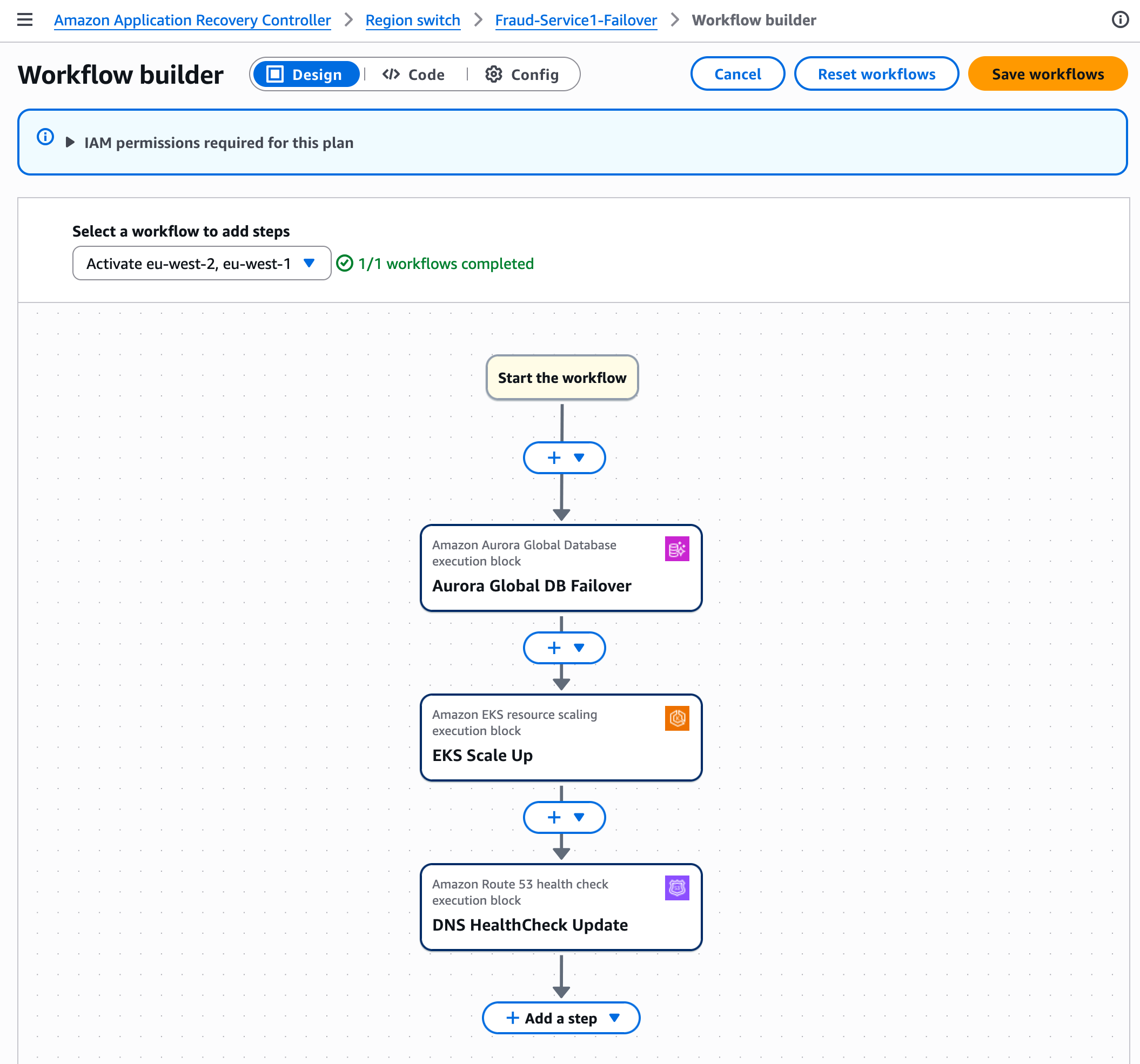
Figure 1: ARC Region Switch runs a plan’s execution blocks from the recovery Region to orchestrate failover
To understand how ARC Region Switch supports this self-service capability within the constraints of centralized ingress controls, we need to examine the underlying infrastructure. The architecture relies on a shared responsibility model where infrastructure and application teams each control distinct layers of the stack, creating clear boundaries that preserve security while supporting operational independence.
Building the foundation: Centralized networking with decentralized control
The architecture rests on two foundational elements: centrally managed AWS Transit Gateways and an application-team-owned Amazon Route 53 Private Hosted Zone (PHZ).
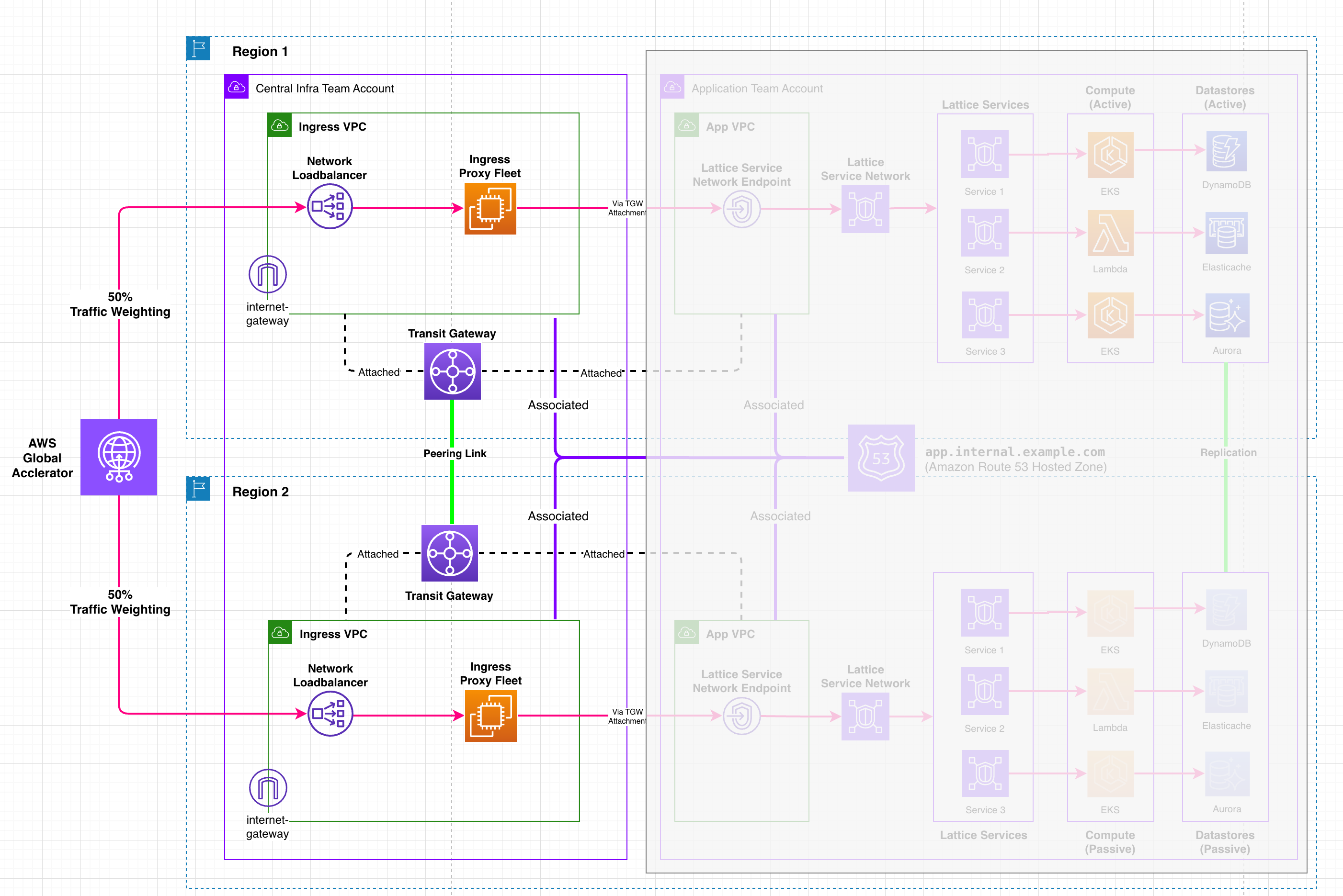
Figure 2: Centrally managed Transit Gateways with an application-team-owned Route 53 Private Hosted Zone
A central infrastructure team owns and manages the peered Transit Gateway infrastructure in both AWS Regions, providing VPC attachments to each application team account so traffic can flow from their secure ingress proxy solution. The application team owns and manages a Route 53 PHZ, associated with all four VPCs: both the infrastructure team’s centralized ingress proxy fleet VPCs and the application team’s own VPCs in each Region. This PHZ contains a failover recordset that the ingress proxy fleet uses to resolve the active application endpoint.
This establishes a clear technical boundary. The infrastructure team provides the secure networking foundation and VPC attachments. The application team controls the Domain Name System (DNS) records that determine where traffic flows. Neither team needs to coordinate changes with the other during failover events.
Understanding the multi-Region architecture
To understand how these components work together, let’s examine the complete architecture. The following diagram illustrates the multi-Region design, showing how AWS Global Accelerator, cross-Region AWS Transit Gateway peering, Amazon VPC Lattice, and Amazon Route 53 Private Hosted Zones combine to support self-service failover through Amazon ARC Region Switch while maintaining centralized security controls.
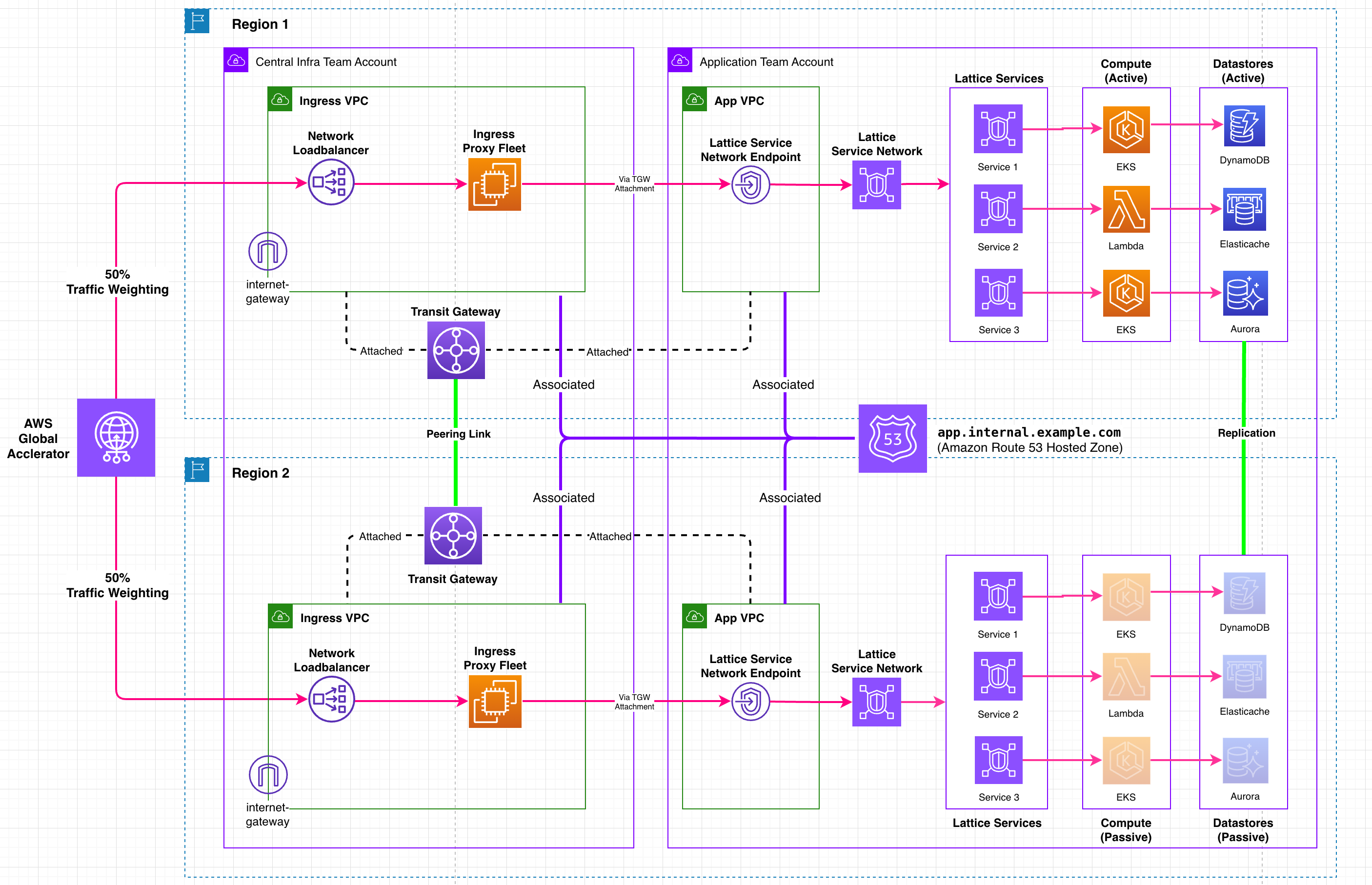
Figure 3: Multi-Region architecture combining Global Accelerator, Transit Gateway peering, VPC Lattice, and Route 53 to support self-service failover
AWS Global Accelerator provides static anycast IPs for the ingress proxy fleet. The 50/50 traffic weighting reflects the platform’s multi-tenant design. Because the centralized ingress proxy fleet serves multiple application teams simultaneously, it must be able to route traffic to applications running in either Region, or active-active across both.
The goal of AWS Global Accelerator is to route traffic to the closest point of presence. If your application is active in Region 1 but a consumer is closer to Region 2, traffic routes to the Region 2 endpoint first, then traverses the cross-Region Transit Gateway peering connection to reach the active application.
The architectural trade-off
This represents an intentional trade-off: accepting an additional network hop through Transit Gateway peering in exchange for true self-service failover. Without this cross-Region connectivity, application teams would need to coordinate with infrastructure teams during failover, reintroducing the exact coordination dependency this architecture seeks to remove.
Fine-grained failover control with Amazon VPC Lattice service network endpoints
While the architecture we’ve described supports independent regional failover, Amazon VPC Lattice service network endpoints add another layer of flexibility worth highlighting: fine-grained control over which services fail over.
Each service network endpoint acts as a consolidated endpoint that can host multiple VPC Lattice services behind it. When you associate a Lattice service with a service network endpoint, it receives its own unique Regional DNS name. For example, an authentication service and a payments service hosted behind the same endpoint each receive distinct DNS names. These per-service DNS names each map to a Route 53 Private Hosted Zone failover record set, giving each service its own independent failover control.
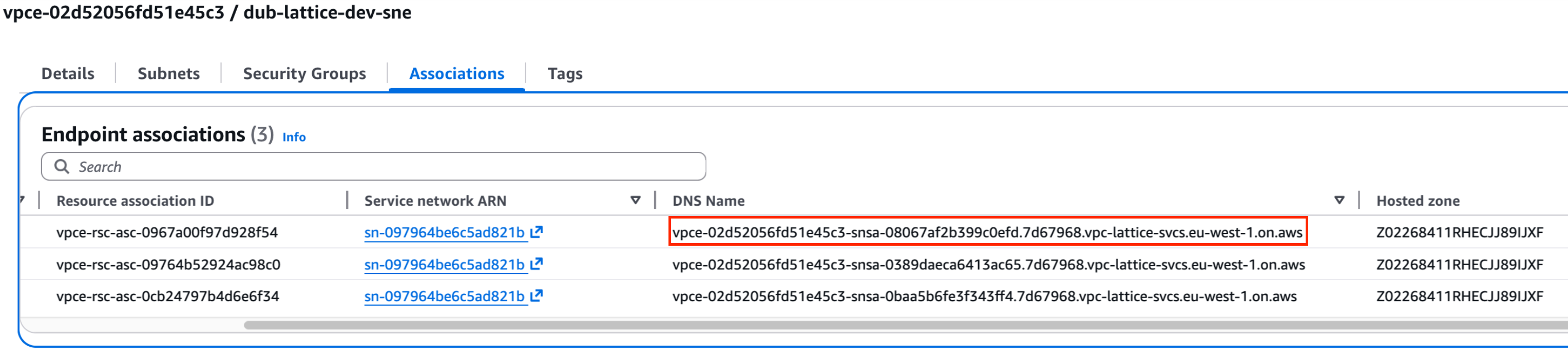
Figure 4: Each VPC Lattice service behind a service network endpoint maps to its own Route 53 failover record set
The key benefit is fine-grained control: application teams can fail over individual Lattice services one at a time, rather than being forced to flip every service behind the same service network endpoint at once. You can validate your authentication service this week, your payment processing service next week, and your inventory service the week after. Each has its own dedicated failover record set in your PHZ, and each is tested without affecting services still running in the primary Region.
This component-level approach requires the least operational overhead, but it carries a risk of bi-modal behavior, where a workload performs differently, with different response times or processes, under normal conditions versus failure modes. Each independent failover adds another active/standby combination, and each must tolerate the cross-Region latency when a service calls a dependency now in the other Region. Design your components to be resilient to this latency and test the realistic combinations. Component-level failover is best suited to teams who have that confidence, so where you don’t, a coarser-grained approach might be the safer choice.
Operationally, the boundary stays clean. The infrastructure team’s ingress proxy fleet continues resolving through the service network endpoint, while the application team controls which services are active in which Region by managing the health check on each service’s DNS record in their PHZ. As your application grows, you associate new microservices with the existing service network endpoint and add their failover record sets, with no changes required to the infrastructure team’s proxy configuration or VPC attachments.
Note: While this post demonstrates a pattern using Amazon VPC Lattice as the application endpoint target, the same shared responsibility approach works regardless of your application stack. Whether you’re running containers on EKS, serverless functions, or traditional EC2 workloads behind Application Load Balancers or Network Load Balancers, the foundational pattern of centralized networking with decentralized DNS control applies equally.
How an application team fails over independently
When the application team runs their ARC Region Switch plan, traffic shifts between Regions without any involvement from the central infrastructure team.
Each application team can independently test their failover capability at their own cadence, as frequently as they choose. These tests are completely independent: one team’s DR exercise has no impact on any other team’s services. As noted in the preceding section, teams should validate the realistic combinations of failed-over and in-place services rather than only the all-in-one-Region baseline.
The failover sequence
What makes this powerful is that it’s a single orchestrated flow, not a set of manual steps. ARC Region Switch runs each block, verifies it has completed successfully, and only then manages the transition to the next, so the sequence advances deterministically, with no human stitching steps together under pressure.
1. Plan initiation. The application team runs their Region Switch plan through the AWS Command Line Interface (AWS CLI) or API, whether for a scheduled DR test or in response to a real incident. The application team can also set up CloudWatch alarms to trigger plans automatically, then run either fully automatically, with no human intervention required, or with a manual approval step built into the workflow that gives teams control to gate execution at critical points.
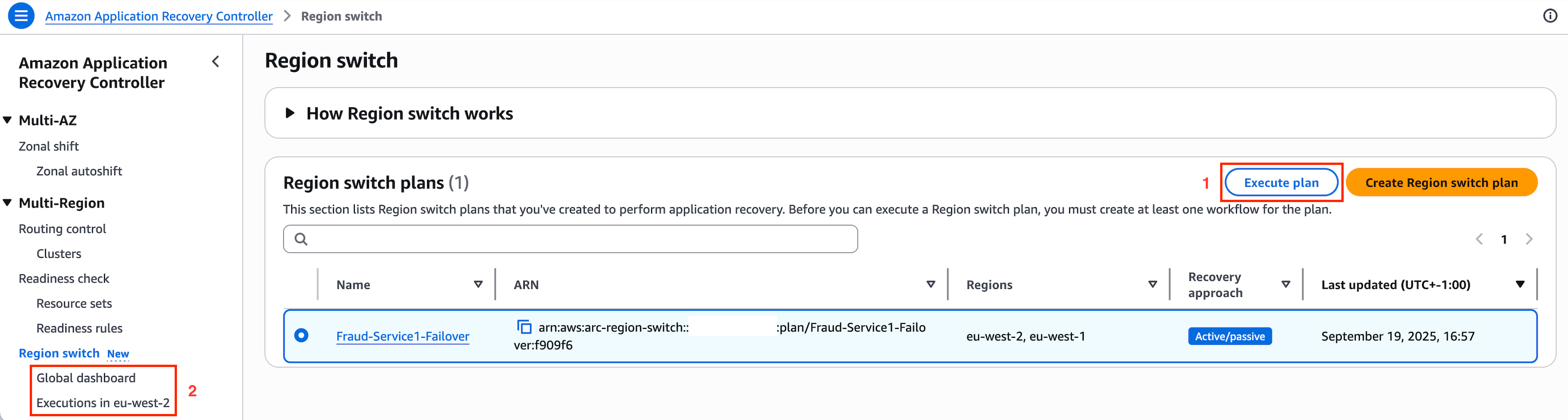
Figure 5: Plan initiation through the AWS CLI or API, with optional CloudWatch alarm triggers and a manual approval step
Note: While plans can be built and run through the AWS console (useful during initial testing), the best practice for real DR invocations is to use the Region Switch API or AWS CLI directly. This reduces cross-service dependencies in your critical path and makes sure your recovery execution doesn’t rely on console availability.
2. Database failover. The first execution block initiates the database transition, promoting the secondary Region’s database to become the primary writer. ARC Region Switch supports both switchover and failover for Amazon Aurora Global Database, RDS instances with cross-Region read replicas, and Amazon DocumentDB (with MongoDB compatibility) clusters. For databases beyond these, such as Amazon DynamoDB global tables, execution blocks can invoke custom Lambda functions to handle service-specific failover logic.
3. Application stack scales up. Subsequent execution blocks handle application infrastructure: scaling compute resources in the standby Region (EKS pods, ECS tasks, or EC2 Auto Scaling groups) and invoking Lambda functions for application-specific logic, such as warming application-level caches so the standby Region doesn’t serve its first requests from a cold cache. This makes sure the standby Region is fully prepared to handle production traffic before any DNS changes occur.
4. Route 53 health check manipulation. After the application stack is ready, ARC Region Switch marks the primary Region’s health check as unhealthy through the native Route 53 health check block, or flips state through an ARC routing control block, triggering Route 53’s failover record logic and redirecting traffic to the now-ready standby Region. You can monitor the current status on the Region Switch plan’s monitoring tab.
Completing the failover: With the health check marked unhealthy, Route 53’s failover mechanism activates. After DNS time-to-live (TTL) values expire, the ingress proxy fleet’s queries resolve to the standby Region’s endpoint. The infrastructure team never needs to reconfigure proxies, update routing rules, or modify DNS records. The application team controls traffic flow through the PHZ record’s health check state by using ARC.
Failback: Returning traffic to the original primary Region works exactly the same way: you trigger your failback plan. Because the design is symmetric, the plan scales the original Region, transitions databases back, and redirects traffic through the same orchestrated flow, in the opposite direction. Failback is as automated, tested, and repeatable as the failover itself.
For more information about creating your own ARC Region Switch plan, refer to the service documentation and the introductory blog post.
From independent to coordinated recovery across the portfolio
The pattern described in the preceding section gives each application team independent failover capability. In practice, however, applications rarely exist in isolation. A payments service depends on an authentication service, and a customer portal depends on an API gateway. When interdependent applications need to recover, they must do so in dependency order. Without a mechanism to coordinate this sequence, the answer today is humans in a war room making phone calls.
Most enterprises capture these dependencies in IT service management (ITSM) tools and wikis, but documentation isn’t orchestration. The worst moment to discover that your dependency maps are stale or your runbooks don’t work is in the middle of a major incident.
Federated recovery with AWS RAM-shared plans
With AWS RAM, you can share Region Switch plans across AWS accounts. Each application team shares its plan from its spoke account with a central hub account, where it’s added as a child plan of a parent plan. Using the Region Switch plan execution block, the parent plan runs each child plan as a step in its workflow. This creates explicit, executable dependency chains between independently owned recovery plans.
Application Team A and Application Team B both share their plans with the hub. The parent plan runs Team A’s plan first, and only when it completes successfully does it run Team B’s plan, so Team B fails over only after its upstream dependencies are ready to serve requests in the recovery Region.
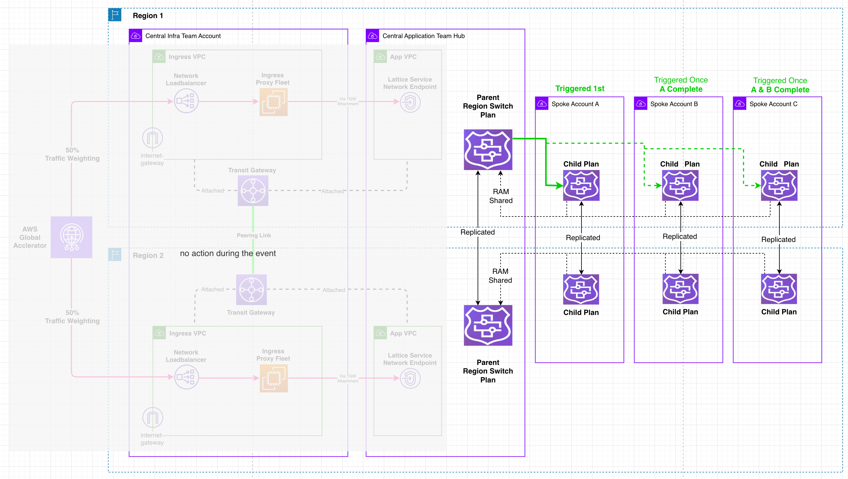
Figure 6: A central parent plan runs each team’s shared child plan in dependency order
These chains can extend across the portfolio (A, then B, then C, with independent applications running in parallel), modeling the full dependency graph as ordered steps in a single parent plan. Each child plan remains independently owned, versioned, and testable by its respective team. The AWS RAM share governs only the hub’s access to the plan, not the plan’s contents or execution logic.
Portfolio-level recovery
The result is deterministic, dependency-ordered portfolio recovery initiated by a single action. A central function triggers the parent plan, and the child plans run in the order it defines. Each child plan can be tested independently by its owning team, and the full parent plan exercised end-to-end during planned DR events, proving coordinated recovery works before it’s needed under pressure.
This addresses a question that enterprises across regulated industries are increasingly asking: “How do we press a big red button to reach our minimum viable business?” A single monolithic recovery script cannot work, because no central team understands every application’s recovery requirements. Parent and child plans solve this: each team owns their recovery logic and maintains it as part of their software development lifecycle (SDLC), keeping it in step with the application it protects, while the parent plan runs them in the correct sequence.
Post-recovery workflows: What happens after failover
Failover isn’t the end of the story. It’s the beginning of recovery operations. After traffic is successfully serving from the new active Region, teams need to run post-recovery workflows to stabilize the environment, validate health, and prepare for eventual failback. Region Switch supports these through additional execution blocks that run after the primary failover sequence completes.
Validation and health confirmation
- Application health checks – Invoke Lambda functions that run synthetic transactions against the newly active stack, verifying API response codes and end-to-end data flow. This measures real recovery time: not when the plan finished, but when requests actually started succeeding again.
- Data integrity verification – Validate that database promotion completed cleanly, check replication lag resolution, and confirm write availability.
- Dependency validation – Verify that downstream services and third-party integrations are responding correctly from the new Region.
Operational stabilization
- Scaling adjustments – Fine-tune Auto Scaling desired counts, EKS Horizontal Pod Autoscaler (HPA) targets, or ECS replica counts based on actual traffic patterns.
- Alerting reconfiguration – Update CloudWatch alarm thresholds and notification routing to reflect the new active Region.
- Standby preparation – Begin provisioning the former primary Region as the new standby.
Notification and compliance reporting
For regulated enterprises, post-recovery documentation is as important as the failover itself:
- Automated notifications – Trigger SNS notifications or Lambda functions that update incident management systems with completion status and duration metrics.
- Compliance evidence – Produce audit-ready logs documenting the failover sequence: what ran, when, which resources were affected, and total recovery time achieved.
- Stakeholder communication – Automatically distribute status updates confirming successful recovery.
Preparing for failback
Post-recovery workflows also set the stage for an eventual return to the original primary Region:
- Replication re-establishment – Confirm that database replication is flowing in the new direction (from new primary to new standby) and monitor replication lag.
- Standby readiness verification – Confirm the former primary Region is healthy and scaled to accept traffic, so it’s ready when failback is needed.
- Failback plan validation – Check the plan evaluation status of your failback plan. Region Switch evaluates it automatically several times an hour, so any warnings about permissions, resources, or capacity are visible before you need to return traffic.
Because these post-recovery steps are defined as execution blocks within the same Region Switch plan, they benefit from the same automation, visibility, and IaC management as the failover itself, with no separate runbooks or manual checklists required. The entire lifecycle, from initial trigger through failover, validation, stabilization, and failback preparation, is captured in a single, version-controlled, repeatable plan.
Conclusion: Reconciling security and autonomy in enterprise cloud architecture
In regulated industries, the tension between centralized security controls and application team autonomy isn’t solved by choosing one over the other. It’s an architectural challenge that demands both. Defense-in-depth strategies with centralized ingress controls are non-negotiable. But modern cloud operations require that teams accountable for availability can act independently when it matters most.
This architectural pattern using Amazon Application Recovery Controller Region Switch delivers the following:
- Application team autonomy – Teams run DR tests, respond to incidents, and meet RTO commitments independently, with no tickets, coordination meetings, or waiting. Application teams control their recovery orchestration while operating within the guardrails of the shared responsibility model.
- Preserved security posture – Centralized ingress controls remain unchanged. The proxy fleet continues enforcing authentication, authorization, threat detection, and audit logging. Application teams never need access to proxy configurations. They only need to control their own PHZ records.
- Automated coordination – Route 53, VPC Lattice, and downstream infrastructure react to ARC-orchestrated changes without manual intervention. Traffic shifts by changing health check state rather than editing DNS records, so recovery relies on highly available data plane operations instead of control plane APIs, in line with Well-Architected guidance. The shared responsibility boundary is enforced through IAM policies and VPC associations, not manual processes.
- Federated portfolio recovery – A central parent plan runs each team’s shared child plan in dependency order, initiated by a single action. Each team retains ownership of their recovery logic while Region Switch coordinates execution across organizational boundaries. Where human oversight is required, a manual approval execution block can gate any step, so automation never removes a team’s control over its own failover.
Because ARC Region Switch is fully managed and highly available, with its data plane operating independently in each Region, application teams can trust that their failover orchestrator is operational precisely when they need it most. And because plans are defined declaratively and can be managed as IaC, teams avoid the maintenance burden of keeping custom scripts synchronized across Regions.
For organizations operating under strict compliance frameworks, this pattern offers a practical blueprint for modernizing disaster recovery without compromising security controls. You don’t need to choose between security and agility. You can architect for both.
Getting started
If your organization operates a similar centralized ingress architecture and wants to support self-service failover:
- Start small: Create your first ARC Region Switch plan in the visual Workflow Builder for a single non-critical service.
- Define as IaC: Export and manage your plan with AWS CloudFormation or the AWS CLI to integrate with your deployment pipelines.
- Set up automatic triggers: Configure CloudWatch alarms to initiate plans automatically, reducing your effective RTO.
- Validate incrementally: Use VPC Lattice (or per-service ALB/NLB records) to test failover for individual services before expanding to full-stack DR exercises.
- Measure and iterate: Track failover duration, identify bottlenecks, and refine your execution blocks.
For the full walkthrough, see the Region Switch tutorial.